
1. With reference to ship’s side valves:
(a) state why grey cast iron is not a suitable material; (4)
(b) state, with reasons, THREE suitable materials. (6)

(a) Define the meaning of the term alloy, stating why they are used. (3)
(b) Describe the changes in the mechanical properties of steel with increasing amounts of carbon. (4)
(c) List SIX common alloying elements used in the production of steel. (3)

1. (a) Define the term stainless steel, making reference the percentage quantities of its TWO main constituents. (4)
(b) With reference to EACH of the following grades of stainless steel, list ONE of its unique properties and a common use that utilises this property: (i) ferritic; (2) (ii) austenitic; (2) (iii) martensitic.

With reference to austenitic stainless steels:
(a) list the THREE main constituents with approximate percentage composition; (3)
(b) state the main difference between grades 304 & 316 and how this is achieved; (3)
(c) list TWO typical applications for EACH grade stated in part (b) that would be found on a modern vessel.
With reference to EACH of the following materials, list their percentage composition and a different application for EACH material on board, stating, with reasons, why they are suitable for this application:
(a) cupro-nickel;(2)
(b) aluminium bronze;(2)
(c) admiralty brass;(2)
(d) duralumin;(2)
(e) solder.(2)

State, with reasons, a different material suitable for EACH of the following applications:
(a) a large motor vessel propeller;(2)
(b) a centrifugal pump impeller;(2)
(c) a sea water cooled heat exchanger tube;(2)
(d) a 300mm diameter sea water cooling pipe;(2)
(e) a cylinder head of a small auxiliary engine.(2)

With reference to the heat treatment of steel:
(a) explain which steels this process is best suited to;(2)
(b) explain EACH of the following processes, making reference to mechanical properties and internal structure:
(i) hardening;(4)
(ii) tempering.(4)

(a) Explain how the properties of steel are modified by its carbon content.(2)
(b) Explain EACH of the following terms:
(i) annealing;(3)
(ii) normalising;(3)
(iii) hardening.(2)

With reference to the case hardening of bearing journals:
(a) explain why this process may be carried out;(2)
(b) describe EACH of the following processes:
(i) induction hardening;(3)
(ii) nitriding;(3)
(c) explain why the processes described in part (b) are best suited to this application.(2)

With reference to case hardening steel components:
(a) describe the changes that occur with this process;(3)
(b) explain why it may be required;(2)
(c) describe EACH of the following processes:
(i) a simple shipboard process;(3)
(ii) solid pack carburising.(2)

With reference to aluminium:
(a) explain what is meant by work hardening;(2)
(b) describe the internal changes when it becomes work hardened;(2)
(c) state the effect work hardening has on its properties;(2)
(d) describe how it could be annealed on board a vessel.(4)

Describe the heat treatment process EACH of the following components would undergo, stating the reasons for EACH of the processes:
(a) crankshaft;(4)
(b) valve spring;(3)
(c) used copper washer.(3)

With reference to the hull of a vessel:
(a) define the term fatigue;(3)
(b) describe how fatigue stress occurs whilst in a seaway;(3)
(c) state the effect of fatigue on the hull material.(4)

With reference to fatigue failure of components:
(a) describe how material fatigue testing is carried out in the laboratory. (2)
(b) sketch the surface appearance of a fatigue fracture;(2)
(c) describe the THREE stages of the failure;(3)
(d) list the methods available on board to limit the possibility of fatigue failure to a propeller shaft.(3)

(a) List FOUR methods for non-destructive crack detection.(4)
(b) Describe TWO procedures from the methods listed in part (a). (6)

(a) Describe TWO destructive tests that a sample of metal intended for the manufacture of a propeller shaft, would undergo before being accepted by a classification society.(6)
(b) Explain the term safety coefficient (factor of safety), stating why it is required.(3)
(c) State a typical safety coefficient designed into a propeller shaft.(1)

With reference to the installation of copper pipes in engine cooling systems:
(a) describe THREE possible causes for their premature failure;(6)
(b) outline FOUR recommendations for the installation of copper pipes (4)

(a) Describe how a Brinell hardness test is carried out.(3)
(b) With reference to a ball race bearing, explain EACH of the following terms:
(i) brinelling;(2)
(ii) false brinelling.(2)
(c) Explain how false brinelling can be reduced in practice.(3)
With reference to stresses within engineering materials:
(a) explain EACH of the following terms
(i) tensile stress; (1)
(ii) shear stress; (1)
(iii) compressive stress; (1)
(b) list TWO components within a diesel engine that are subject to the effects of EACH of the three stresses listed in part (a); (6)
(c) state the component in a 4 stroke diesel engine that has a maximum recommended service life due to constant cyclic stress. (1)

(a) Explain EACH of the following terms:
(i) plasticity;(2)
(ii) sheer stress;(2)
(iii) Young’s modulus;(2)
(iv) safety coefficient (factor of safety).(2)
(b) State TWO factors that may influence the safety coefficient in operation.(2)

Explain EACH of the following terms:
(a) ductile cast iron;(2)
(b) tensile stress;(2)
(c) work hardening;(2)
(d) shear stress;(2)
(e) Young’s modulus.(2)

Describe, with the aid of load extension graphs, EACH of the following engineering terms:
(a) limit of proportionality;(2)
(b) yield point;(2)
(c) Ultimate Tensile Strength;(2)
(d) 0.1% Proof Stress.(4)

Explain EACH of the following engineering terms:
(a) hardness;(2)
(b) proof stress;(2)
(c) ultimate tensile strength (UTS);(2)
(d) Young’s Modulus;(2)
(e) yield stress.(2)

Explain EACH of the following engineering terms, stating ONE material that exhibits EACH property:
(a) brittleness;(2)
(b) ductility;(2)
(c) hardness;(2)
(d) malleability;(2)
(e) toughness.(2)

With reference to the production of glass reinforced plastic (GRP) hulls:
(a) outline the properties of glass fibre and resin that make them suitable for the construction of a hull;(3)
(b) describe the traditional method for the layup of a GRP hull;(5)
(c) list FOUR disadvantages of GRP hulls in service.(2)

With reference to the production of glass reinforced plastic (GRP) hulls:
(a) describe the process of resin infusion moulding for the production of a hull;(4)
(b) state the advantages of resin infusion moulding with respect to traditional methods of construction;(3)
(c) explain how this process can virtually eliminate the onset of osmosis in the hull.(3)

With reference to osmosis in glass reinforced plastic (GRP) hulls:
(a) explain the process of osmosis and the method by which osmotic blisters occur in service;
(6)
(b) describe a procedure for the local treatment of a single blister.(4)

With reference to osmosis in glass reinforced plastic (GRP) hulls:
(a) explain how osmosis may be detected in service;(2)
(b) explain why simply drying out the hull is not a cure for the effects of osmosis;(2)
(c) describe the FULL process for the treatment of a hull suffering from the effects of osmosis.(6)

With reference to in service defects found in glass reinforced plastic (GRP) hulls:
(a) state THREE possible causes of de-lamination;(3)
(b) describe TWO methods of detecting de-lamination in service;(2)
(c) describe TWO methods of repair to de-lamination on a sandwich construction hull;(2)
(d) list THREE design problems that can lead to stress cracking.(3)

With reference to glass reinforced plastic (GRP) hulls:
(a) state THREE causes for EACH of the following defects to occur:
(i) de-lamination;(3)
(ii) osmotic blisters;(3)
(iii) stress cracking;(3)
(b) state the part of the underwater section of the hull on which osmotic blisters most commonly occur.(1)

With reference to root whitening in GRP hull construction:
(a) explain the term root whitening, stating where it is most likely to occur;(2)
(b) explain TWO possible reasons why this may happen;(4)
(c) state TWO possible actions that could be taken if it is discovered.(4)

With reference to carbon fibre:
(a) describe how the base raw material is turned into a useable carbon fibre;(2)
(b) describe how the fibres produced in part (a) are turned into a usable product;(2)
(c) explain how its internal structure gives it its unique strength properties;(2)
(d) list FOUR properties of carbon fibre that make it desirable for marine fabrication.(4)

With reference to the manufacture of carbon fire components:
(a) describe EACH of the following processes and its advantages:
(i) vacuum bagging;(2)
(ii) autoclave curing;(2)
(iii) resin transfer moulding;(3)
(b) list the type of component that EACH process described in part (a) is best suited to.(3)

With reference to carbon fibre used in marine construction:
(a) describe the properties that make it suitable for EACH of the following:
(i) hull construction;(2)
(ii) mast construction;(2)
(b) explain its undesirable properties for the applications in part (a);(3)
(c) explain the safety considerations necessary when working with carbon fibre.(3)

(a) Describe the problems associated with two dissimilar metals in contact in the presence of sea water.(4)
(b) Describe THREE different methods that may be used to reduce the problems described in part (a).(6)

With reference to marine corrosion:
(a) list EIGHT factors that influence the rate of corrosion for an unprotected metal surface;(4)
(b) explain the process of galvanic corrosion;(4)
(c) state TWO major factors influencing the severity of galvanic corrosion.(2)

With reference to the cathodic protection of hull fittings:
(a) explain how sacrificial anodes achieve this;(2)
(b) state where sacrificial anodes would be fitted and why;(4)
(c) describe an impressed current system, stating the principle on which it works.(4)

Explain how corrosion and its effects can be minimised in seawater cooling systems.(10)

With reference to hot docking:
(a) explain how this occurs, stating its effects;(6)
(b) describe the operation of TWO devices that will prevent this occuring.(4)
(a) With reference to fretting corrosion:
(i) explain the process;(3)
(ii) state a common cause;(1)
(iii) state how it is normally detected.(1)
(b) With reference to pitting corrosion:
(i) explain the term pitting corrosion;(1)
(ii) state TWO common causes;(2)
(iii) explain why it is considered to be dangerous.(2)

Explain EACH of the following terms:
(a) galvanic corrosion;(2)
(b) cavitation damage;(2)
(c) erosion damage;(2)
(d) stress corrosion;(2)
(e) atmospheric corrosion.(2)

A vessel has been laid up for a considerable time with shore power connected. Routine underwater hull inspections reveal an unusually high deterioration rate of the vessel’s anodes. Assuming the dockside wiring, shore power connections and bonding systems are all in good condition and correctly connected:
(a) explain how this may occur;(8)
(b) state TWO devices that should be fitted to prevent this situation occurring.(2)

A drydock inspection of the stainless steel alloy propeller shafts has revealed serious pitting corrosion of the shafts in the region where the shafts pass through the stern tube. The stern tube arrangement consists of a shaft seal and a sea-water flooded stern tube with cutless bearing at the aft (sea) end.
(a) Describe the possible reasons for this corrosion.(6)
(b) Describe the modifications that could be made to the stern tube arrangement to reduce the likelihood of future shaft corrosion.(4)

With reference to oxy-acetylene welding:
(a) describe the process;(2)
(b) explain why it is important to get the gas mixture correct;(3)
(c) list the design safety features and inspections to be carried out on the welding torch and cylinders before commencing welding.(5)

With reference to gas metal arc welding (MIG) of mild steel:
(a) describe the process;(3)
(b) explain, with reasons, the surface preparation required;(3)
(c) list THREE advantages and ONE limitation.(4)

With reference to joining a steel hull to an aluminium superstructure:
(a) explain, with the aid of a sketch, the process of explosion welding;(6)
(b) explain why this joint is superior to an insulated bolt joint (4)

(a) Outline THREE disadvantages of using aluminium in vessel construction.(3)
(b) Outline THREE advantages of using steel in vessel construction.(3)
(c) Outline FOUR conditions necessary in the preparation of steel surfaces prior to painting, to ensure a good surface finish.(4)
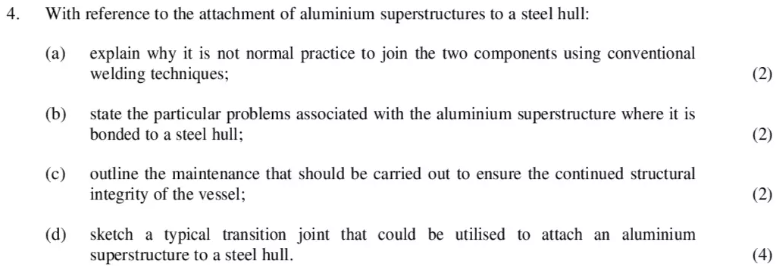
With reference to the attachment of aluminium superstructures to a steel hull:
(a) explain why it is not normal practice to join the two components using conventional welding techniques;(2)
(b) state the particular problems associated with the aluminium superstructure where it is bonded to a steel hull;(2)
(c) outline the maintenance that should be carried out to ensure the continued structural integrity of the vessel;(2)
(d) sketch a typical transition joint that could be utilised to attach an aluminium superstructure to a steel hull.(4)

With reference to TIG welding:
(a) describe the process;(3)
(b) explain why an ac current is preferred when welding aluminium;(2)
(c) explain the advantages compared to other methods.(5)

Describe, with the aid of sketches, FIVE defects that may be present on a weld produced using the covered electrode welding process.(10)
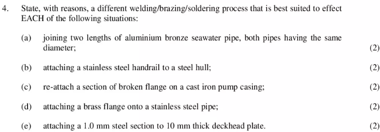
State, with reasons, a different welding/brazing/soldering process that is best suited to effect EACH of the following situations:
(a) joining two lengths of aluminium bronze seawater pipe, both pipes having the same diameter;(2)
(b) attaching a stainless steel handrail to a steel hull;(2)
(c) re-attach a section of broken flange on a cast iron pump casing;(2)
(d) attaching a brass flange onto a stainless steel pipe;(2)
(e) attaching a 1.0 mm steel section to 10 mm thick deckhead plate.(2)

With reference to a PT100 probe (resistance thermometer):
(a) explain the principle of operation by which it is able to give a temperature measurement;(3)
(b) describe how the sensing element is constructed, explaining why it is called a PT100 probe;(4)
(c) explain why these probes typically have three or four wires to connect them to the temperature indicating device.(3)

(a) Explain, with the aid of a sketch, the design and operation of a thermocouple.(8)
(b) State ONE limitation of the thermocouple, stating how this is overcome in practice.(2)

List FIVE different methods of remotely monitoring the content level of a fuel oil service tank, explaining their operating principle.
(10)

(a) Describe with the aid of a sketch, how Bi-metallic strips are utilised to measure temperature.(8)
(b) State a typical application for this type of device and its main shortcoming.(2)

(a) Describe, with the aid of a sketch, the principle and operation of a potentiometer.(6)
(b) Explain how a potentiometer can be used to measure rotary movement.(4)

With reference to a thermistor:
(a) state the materials used in their construction, the principle of operation and the reason for their use on vessels;(4)
(b) state the temperature range over which they are able to operate;(1)
(c) state, with reasons, FIVE applications where thermistors may be found on board a vessel.(5)

(a) Describe, with the aid of a sketch, how a Bourdon Tube can be utilised to measure temperature.(8)
(b) State a typical application and location for this type of device.(2)

Describe, with the aid of a sketch, a method of measuring and remotely indicating EACH of the following:
(a) temperature;(4)
(b) rate of flow.(6)

With reference to an impeller type flowmeter, describe how an output is produced and processed to provide EACH of the following:
(a) an analogue output in litres per minute;(5)
(b) a digital output in litres per minute.(5)

Describe, with the aid of a sketch, a floatation device that produces an output signal to remotely control the liquid level in a tank.
(10)

With reference to capacitance probe sensors:
(a) describe, with the aid of a sketch, how a capacitance probe produces an output which can be used to measure the liquid level in a tank.(7)
(b) state TWO different uses of this device on a vessel:(2)
(c) state ONE disadvantage of this type of probe.(1)

(a) Explain, with the aid of a sketch, how the fluid level in a tank can be measured using ultrasound energy.(6)
(b) State TWO advantages of using ultrasound.(2)
(c) State TWO limitations of this type of measuring device.(2)

With reference to strain gauges:
(a) describe, with the aid of a sketch, the principle and operation of a simple strain gauge, stating the formula used to determine its change in properties;(5)
(b) explain how the device is connected into an electrical circuit to accurately measure pressure;(3)
(c) state TWO practical applications in a vessel.(2)
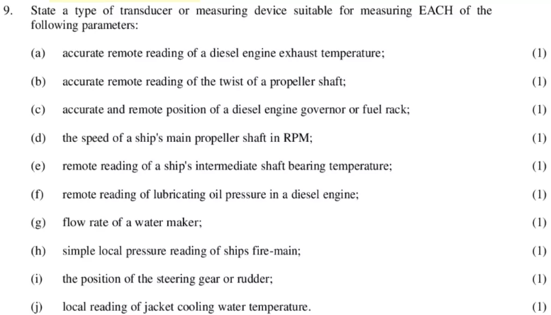
State a type of transducer or measuring device suitable for measuring EACH of the following parameters:
(a) accurate remote reading of a diesel engine exhaust temperature;(1)
(b) accurate remote reading of the twist of a propeller shaft;(1)
(c) accurate and remote position of a diesel engine governor or fuel rack;(1)
(d) the speed of a ship’s main propeller shaft in RPM;(1)
(e) remote reading of a ship’s intermediate shaft bearing temperature;(1)
(f) remote reading of lubricating oil pressure in a diesel engine;(1)
(g) flow rate of a water maker;(1)
(h) simple local pressure reading of ships fire-main;(1)
(i) the position of the steering gear or rudder;(1)
(j) local reading of jacket cooling water temperature.(1)

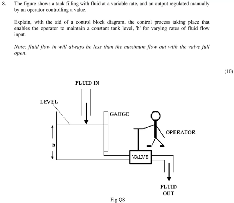
The figure shows a tank filling with fluid at a variable rate, and an output regulated manually by an operator controlling a value.
Explain, with the aid of a control block diagram, the control process taking place that enables the operator to maintain a constant tank level, ‘h’ for varying rates of fluid flow input.
Note: fluid flow in will always be less than the maximum flow out with the valve full open.
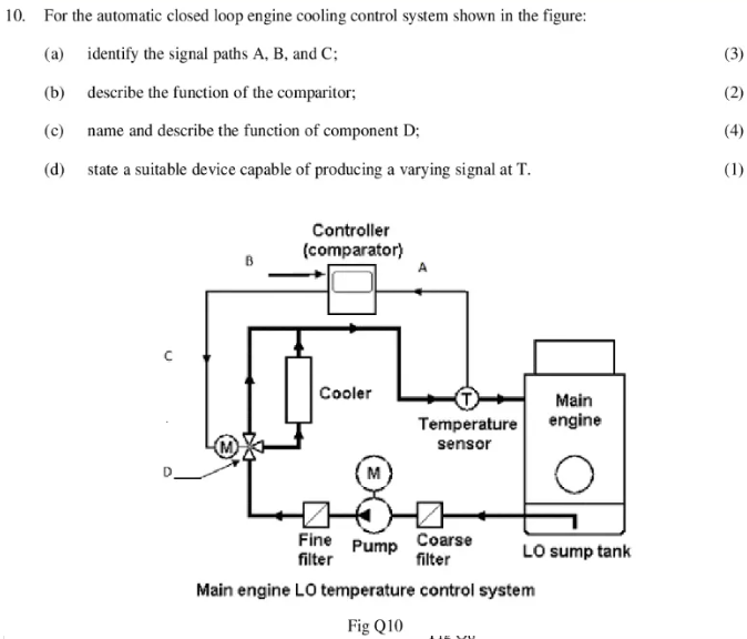
For the automatic closed loop engine cooling control system shown in the figure:
(a) identify the signal paths A, B, and C;(3)
(b) describe the function of the comparitor;(2)
(c) name and describe the function of component D;(4)
(d) state a suitable device capable of producing a varying signal at T.(1)

Explain, with the aid of a diagram, the principle of a cascade control method for regulating the freshwater coolant temperature of a diesel engine.
(10)

(a) Sketch a block diagram of a split range control system, used to control the jacket water temperature of a main engine.(6)
(b) Describe the operation of this system.(4)

(a) Define EACH of the following terms:
(i) cascade control;(4)
(ii) split range control.(3)
(b) Describe possible problems associated with split range control used for the control of a main engine cooling system.(3)
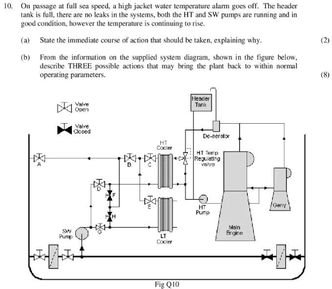
On passage at full sea speed, a high jacket water temperature alarm goes off. The header tank is full, there are no leaks in the systems, both the HT and SW pumps are running and in good condition, however the temperature is continuing to rise.
(a) State the immediate course of action that should be taken, explaining why.(2)
(b) From the information on the supplied system diagram, shown in the figure below, describe THREE possible actions that may bring the plant back to within normal operating parameters.(8)
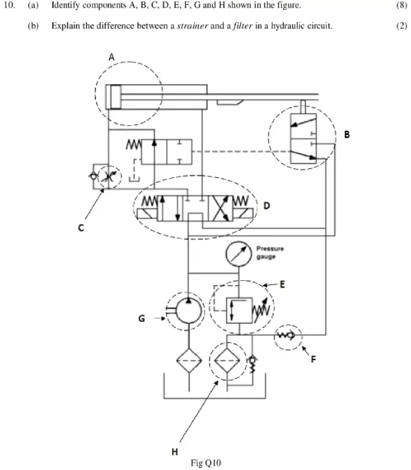
(a) Identify components A, B, C, D, E, F, G and H shown in the figure. (8)
(b) Explain the difference between a strainer and a filter in a hydraulic circuit.
(2)

(a) Explain the term failsafe in a control system, stating TWO examples where this term is applied.(4)
(b) Explain the term failset in a control system, stating TWO examples where this term is applied.(4)
(c) State what is meant by a 4:3 control valve.(2)

With reference to Discontinuous or On Off control systems:
(a) sketch the response of a basic heater control, showing temperature against time and labelling the key points;(4)
(b) state THREE methods of improving the accuracy/speed of response(6)
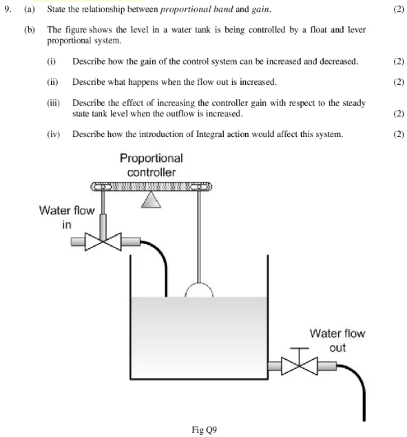
(a) State the relationship between proportional band and gain.
(b) The figure shows the level in a water tank is being controlled by a float and lever proportional system.
(i) Describe how the gain of the control system can be increased and decreased.
(ii) Describe what happens when the flow out is increased.
(iii) Describe the effect of increasing the controller gain with respect to the steady state tank level when the outflow is increased.
(iv) Describe how the introduction of Integral action would affect this system.

(a) Explain EACH of the following control terms:
(i) proportional bandwidth;(2)
(ii) integral action;(2)
(iii) derivative action.(2)
(b) Describe a 3-step method for tuning a PID controller.(4)

(a) Define the term Proportional Action.(2)
(b) Explain the purpose of Integral Action.(2)
(c) Describe a possible effect of excessive Integral Action.(2)
(d) Explain the purpose of Derivitive Action.(2)
(e) Describe the effect of excessive Derivitive Action.(2)

With reference to hydraulic governors fitted to alternators designed to run in parallel:
(a) explain why these governors have adjustable integral action;(5)
(b) explain, with the aid of a load/frequency diagram, how two generators operating in parallel are able to achieve a stable load share with a 50/50 ratio.(5)

(a) Describe, with the aid of a control block diagram, how a governor maintains the speed of a diesel engine driving a generator.(6)
(b) Describe the reasons for Integrating the error signal and the effect it has on the governor fuel rack.(4)
(a) State the reasons for fitting a pneumatic process valve with EACH of the following:
(i) a volume booster;(2)
(ii) a feedback positioner.(2)
(b) State, with reasons, the type of actuator fitted to the process valves for EACH of the following systems:
(i) a fuel supply system in which the valve must not move on loss of power to the control system;(3)
(ii) a lubrication oil cooling system in which the valve diverts the oil through a cooler.(3)

With reference to engine governors, explain EACH of the following terms:
(a) sensitivity;(2)
(b) hunting;(2)
(c) speed droop;(2)
(d) stability;(2)
(e) isochronous governing.(2)

Explain EACH of the following control terms:
(a) settling time;(2)
(b) repeatability;(2)
(c) dead zone;(2)
(d) hysteresis;(2)
(e) proportional bandwidth.(2)
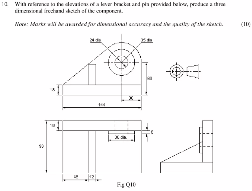
With reference to the elevations of a lever bracket and pin provided below, produce a three dimensional freehand sketch of the component.
Note: Marks will be awarded for dimensional accuracy and the quality of the sketch.