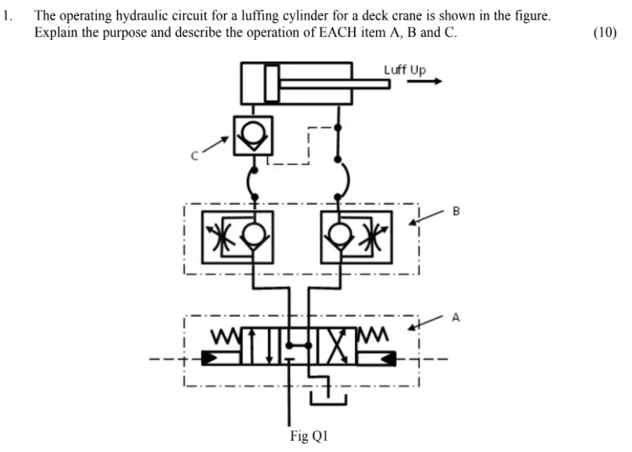
- The operating hydraulic circuit for a luffing cylinder for a deck crane is shown in the figure. Explain the purpose and describe the operation of EACH item A, B and C.
(10) Fig Q1
What is a luffing cylinder?
A luffing cylinder is a hydraulic cylinder used in cranes and other machinery to control the angle of the boom or jib. In essence, it allows the boom to be raised or lowered, which is crucial for positioning the load precisely where it needs to be.
How it works:
- The luffing cylinder is typically attached to the boom near its base and to the crane’s main structure.
- Hydraulic fluid is pumped into the cylinder, causing the piston rod to extend or retract.
- This movement pushes or pulls on the boom, changing its angle relative to the ground.
Importance:
- Luffing cylinders are vital for the precise control of the boom’s position, enabling the crane operator to lift and lower loads safely and accurately.
- They are especially important in applications where the crane needs to work in confined spaces or reach over obstacles.
Example Applications:
- Tower cranes: Used to raise and lower the jib, allowing for greater reach and flexibility.
- Mobile cranes: Used to adjust the boom angle for lifting and placing loads at different heights and distances.
- Offshore cranes: Used on oil rigs and other offshore platforms to handle heavy equipment and supplies.
- Ship cranes: Used for loading and unloading cargo on ships.
Key Features:
- High strength and durability: Luffing cylinders are designed to withstand heavy loads and harsh operating conditions.
- Precision control: They offer smooth and precise control of the boom’s movement.
- Safety features: They are equipped with safety valves and other features to prevent overpressure and ensure safe operation.
In summary, a luffing cylinder is a critical component in cranes and other lifting equipment, enabling the precise control of the boom’s angle and facilitating safe and efficient lifting operations.
Hydraulic circuit for a luffing cylinder for a deck crane
Let’s outline a typical hydraulic circuit for operating a luffing cylinder in a deck crane.
Key Components:
- Hydraulic Pump: Supplies pressurized fluid to the system. This could be a gear pump, vane pump, or piston pump, depending on the crane’s requirements.
- Luffing Cylinder: The double-acting hydraulic cylinder that directly controls the raising and lowering of the crane’s boom or jib.
- Directional Control Valve: A valve that directs the flow of hydraulic fluid to either side of the luffing cylinder, controlling its extension or retraction.
- Relief Valve: Protects the system from excessive pressure by diverting fluid back to the tank if the pressure exceeds a safe limit.
- Check Valves: Prevent backflow of fluid, ensuring the boom maintains its position when the directional control valve is in the neutral position.
- Hydraulic Tank: Stores the hydraulic fluid and allows for heat dissipation.
- Filters: Remove contaminants from the hydraulic fluid to protect the pump and other components.
- Piping and Hoses: Connect the various components of the circuit.
Circuit Operation:
- Raising the Boom (Luffing Up):
- The crane operator actuates the directional control valve to direct pressurized fluid from the pump to the rod-end side of the luffing cylinder.
- The fluid pushes the piston, extending the cylinder rod and raising the boom.
- Fluid from the piston side of the cylinder returns to the tank.
- Check valves prevent backflow, holding the boom in position when the valve is in neutral.
- Lowering the Boom (Luffing Down):
- The operator actuates the directional control valve to direct pressurized fluid to the piston side of the luffing cylinder.
- The fluid pushes the piston, retracting the cylinder rod and lowering the boom.
- Fluid from the rod-end side of the cylinder returns to the tank.
- Again, check valves maintain the boom’s position when the valve is in neutral.
- Pressure Regulation:
- The relief valve continuously monitors system pressure. If the pressure exceeds the set limit (e.g., due to an obstruction or overload), the relief valve opens, bypassing fluid back to the tank to prevent damage to the system.
Additional Features:
- Counterbalance Valves: May be included to prevent the boom from dropping uncontrollably in case of a hose or pipe failure.
- Flow Control Valves: Can be used to regulate the speed of the boom’s movement for smoother and more precise control.
- Pilot-Operated Valves: May be used for remote or automated control of the luffing cylinder.
Safety Considerations:
- Regular Inspections and Maintenance: The hydraulic system and its components should be regularly inspected and maintained to ensure their proper function and prevent leaks or failures.
- Operator Training: Crane operators must be adequately trained in the operation and safety procedures of the luffing system.
- Emergency Stop: The system should have an easily accessible emergency stop button to halt the boom’s movement in case of an emergency.
This is a basic overview of a typical luffing cylinder hydraulic circuit. More complex systems might incorporate additional features like load-sensing control or regenerative circuits to improve efficiency.