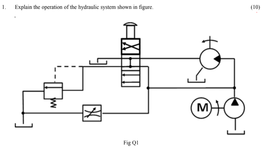
- Explain the operation of the hydraulic system shown in figure.
Fig Q1

- Describe, with the aid of a sketch, a constant pressure hydraulic power system for a vessel’s Anchor Windlass, showing safety features and labelling ALL components of the system.(10)

- (a) Sketch the hydraulic symbol for a directional control valve.(3)
(b) Describe the operation of EACH of the following hydraulic valves:
(i) directional control valve;(2)
(ii) speed control valve;(2)
(iii) brake valve.(3)

2.(a) Explain why a hydraulic actuator is preferred for a vessel’s stabiliser over an electrical actuator.(5)
(b) Sketch a hydraulic circuit for a single stabiliser, suitable for a constant pressure system.(5)

- Describe, with the aid of a sketch, a hydraulic rack and pinion starting system, labelling the MAIN components.
(10)

Question 2.
Some sketch a standard hydraulic system for e.g. a steering gear. Some give no description. Some show a hydraulic motor.

- Sketch a hydraulic system for adjusting the angle of fin stabilisers, labelling ALL parts.(10)