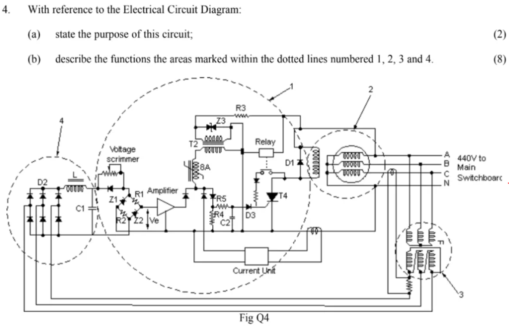
- With reference to the Electrical Circuit Diagram:
(a) state the purpose of this circuit;
(b) describe the functions the areas marked within the dotted lines numbered 1, 2, 3 and 4.
(a) State the purpose of this circuit (2 marks)
This circuit is a three-phase undervoltage (or protective) relay system used to protect the main switchboard (440 V AC) supply.
- It continuously monitors the incoming 3-phase supply.
- If the supply voltage falls below a set limit (undervoltage) or is lost, the relay drops out, disconnecting or preventing automatic reconnection of switchboard loads.
✅ Purpose: To protect electrical machinery/switchboard from undervoltage or supply faults by tripping the contactor and preventing automatic restart.
(b) Describe the functions of the areas marked within the dotted lines numbered 1, 2, 3 and 4 (8 marks)
1 – Control relay and amplifier unit
- Contains an amplifier and relay driver circuit.
- Monitors the rectified and smoothed signal from the voltage sensing circuit.
- If the sensed voltage is below the threshold, the relay de-energises and trips the main contactor.
- Ensures fast disconnection during undervoltage/fault conditions.
2 – Main contactor coils
- Energised by the relay in section 1.
- Controls the connection of the 440 V 3-phase supply to the main switchboard.
- If undervoltage or fault is detected, the coils de-energise, opening the contactors and isolating the supply.
3 – Current unit (overcurrent / protection unit)
- Monitors load current from the outgoing lines.
- Provides overcurrent protection: if excess current is detected, it sends a signal to trip the relay in section 1.
- Prevents damage to cables, switchboard, or connected equipment due to overloads or short circuits.
4 – Voltage sensing and rectifier circuit
- Connected across the incoming 3-phase supply (ABC).
- Uses diodes (D2) to rectify the AC voltage to DC.
- A smoothing capacitor (C1) and voltage divider (Z1, Z2) provide a stable DC reference signal.
- This feeds into the amplifier in section 1 for voltage level comparison.
- Function: To continuously sense the incoming supply voltage and detect undervoltage conditions.